Denon DCD-620 CD player
I got this CD player on Ebay as a job lot with a Marantz CD-38 back in 2009. I bought the Marantz but the Denon was thrown in as a non functional freebie. My original plan was to use it for spare parts (or as a case for my media player project) while the Marantz was to be my Hi-Fi CD deck. However the Marantz vanished while I was moving home leaving me with the faulty Denon. Rather than fix the Denon it sat in storage while I used a DVD player for the occasional CD and afterwards I expected that my Media player project would handle both CD's and streaming.
However since then I found myself rarely using CD's, preferring instead to stream from my server. As a result I decided not to bother implementing CD support in that project.
This article came about as I came across this CD player while de-cluttering my storage. I was sorting stuff into things I will use in future and things I can dispose of. Keeping the CD player in storage was not an option, so I decided to try fixing it and if not possible it will go in my junk box to be used for parts.
It also made me question whether to bother having a CD deck at all. I long since don't have the DVD player hooked up to the Hi-Fi and all my music listening has been via streaming through my media player. If I fix it then my CDs will remain in the living room for listening, otherwise I will junk this deck and the CDs will go into storage as archival backup, only to be pulled out for re-ripping to FLAC as and when needed.
Repairs
First thing I had to do was work out why the VFD was flashing. It was an odd failure mode because you would turn the deck on, the VFD will flash, and if you hit "STOP" it stops flashing and the drive spins up reading the CD. It will then work, unless you eject/load a CD, or you go forward/backward too fast (at which point the deck halts and the VFD starts flashing again).
This behaviour made me think that it was either a logic error (e.g. bit rot in the EPROM of the microcontroller) or a power issue (because it happened during high current draw events like initial power on surge, motor repositioning due to track forwarding/skipping and tray eject/load).
If it was EPROM/logic errors then I probably could not repair it. Even if I could find replacement chips the loss of the original code would not allow the deck to function. Therefore I concentrated on checking the power supply.
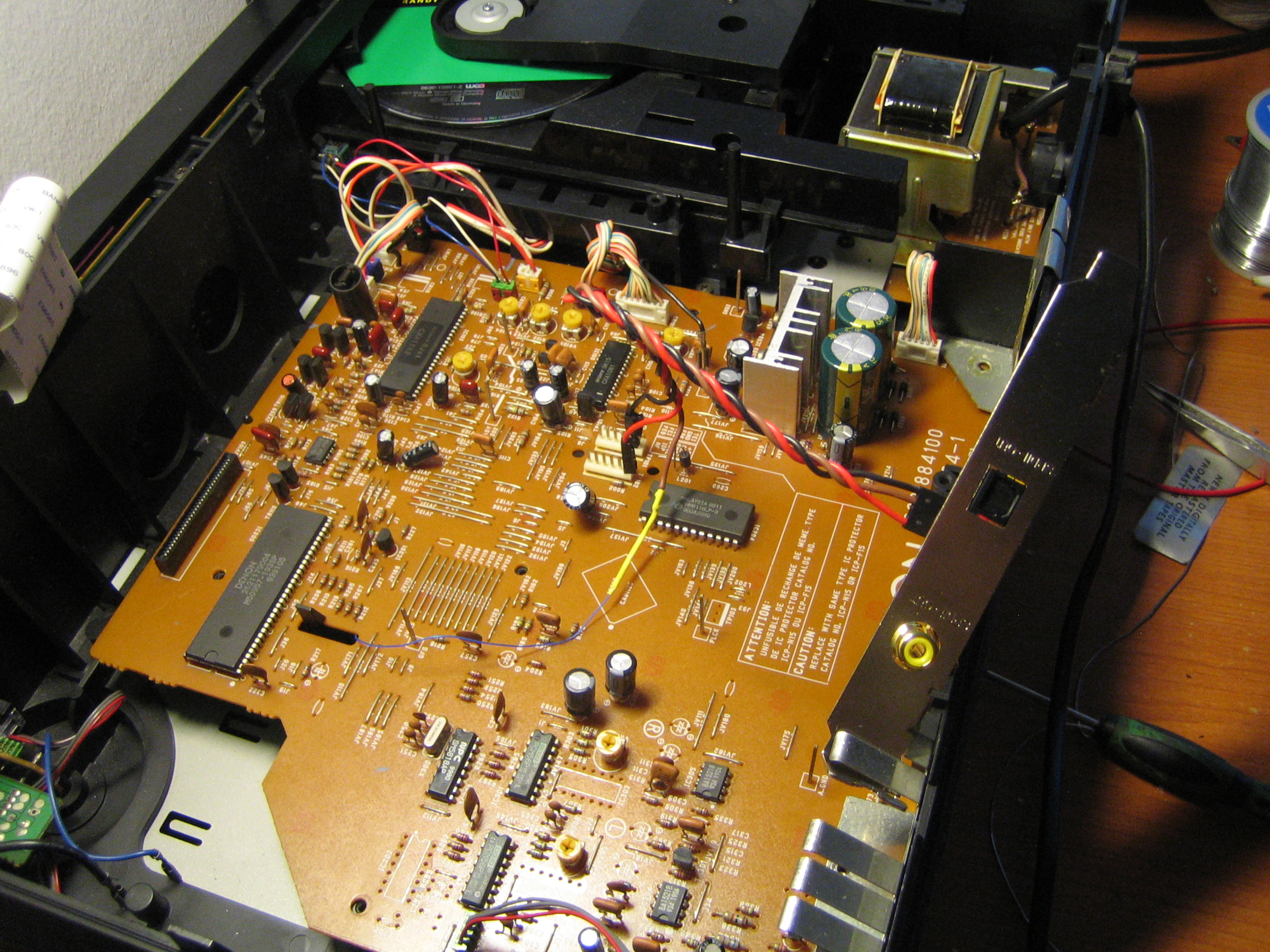
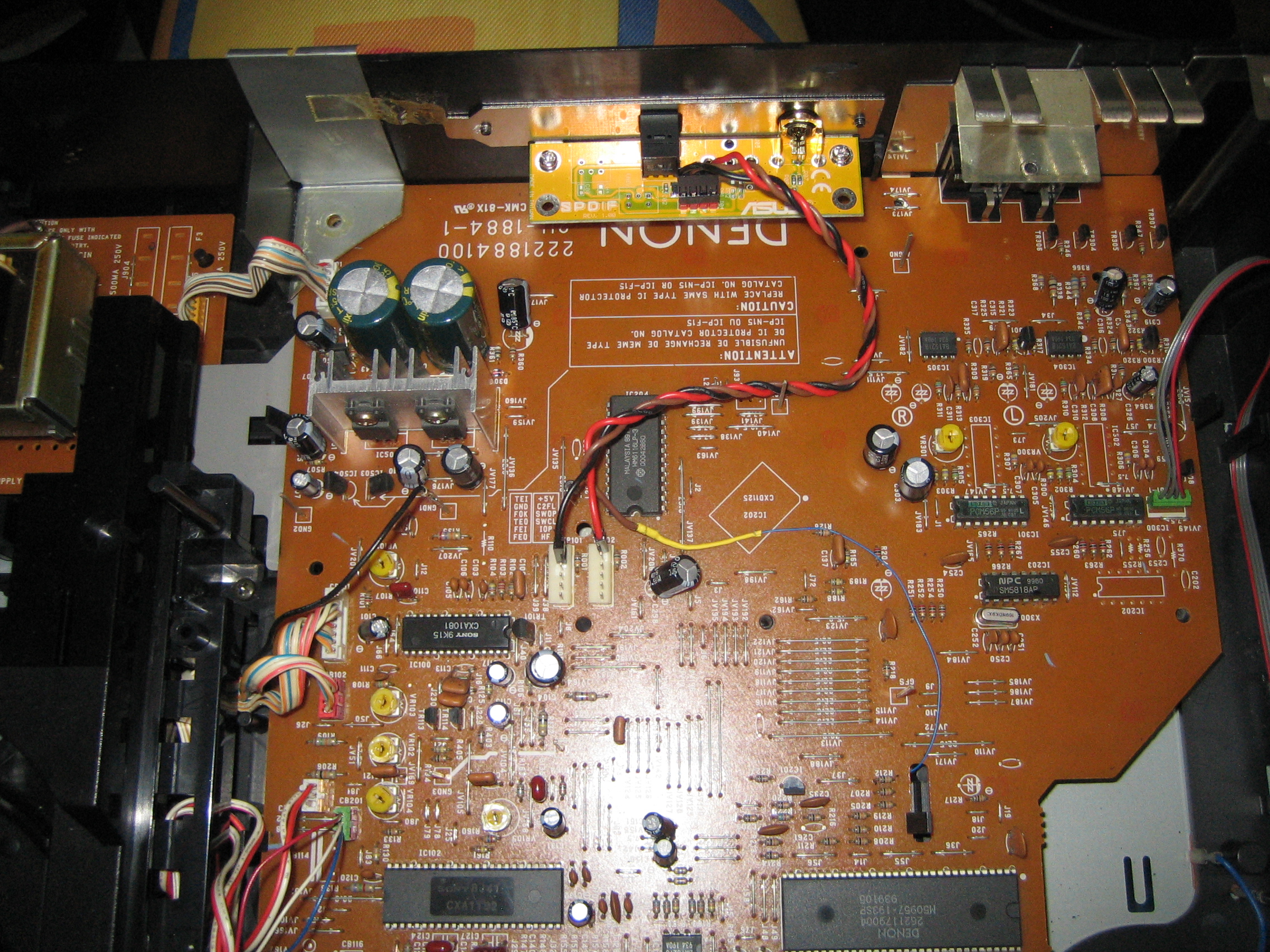
First thing I did was to look inside and check for any swollen/burst capacitors, as that is the most common failure mode. The top of the DCD comes off quite easily, showing us the mechanism on the left, and the logic board on the right:
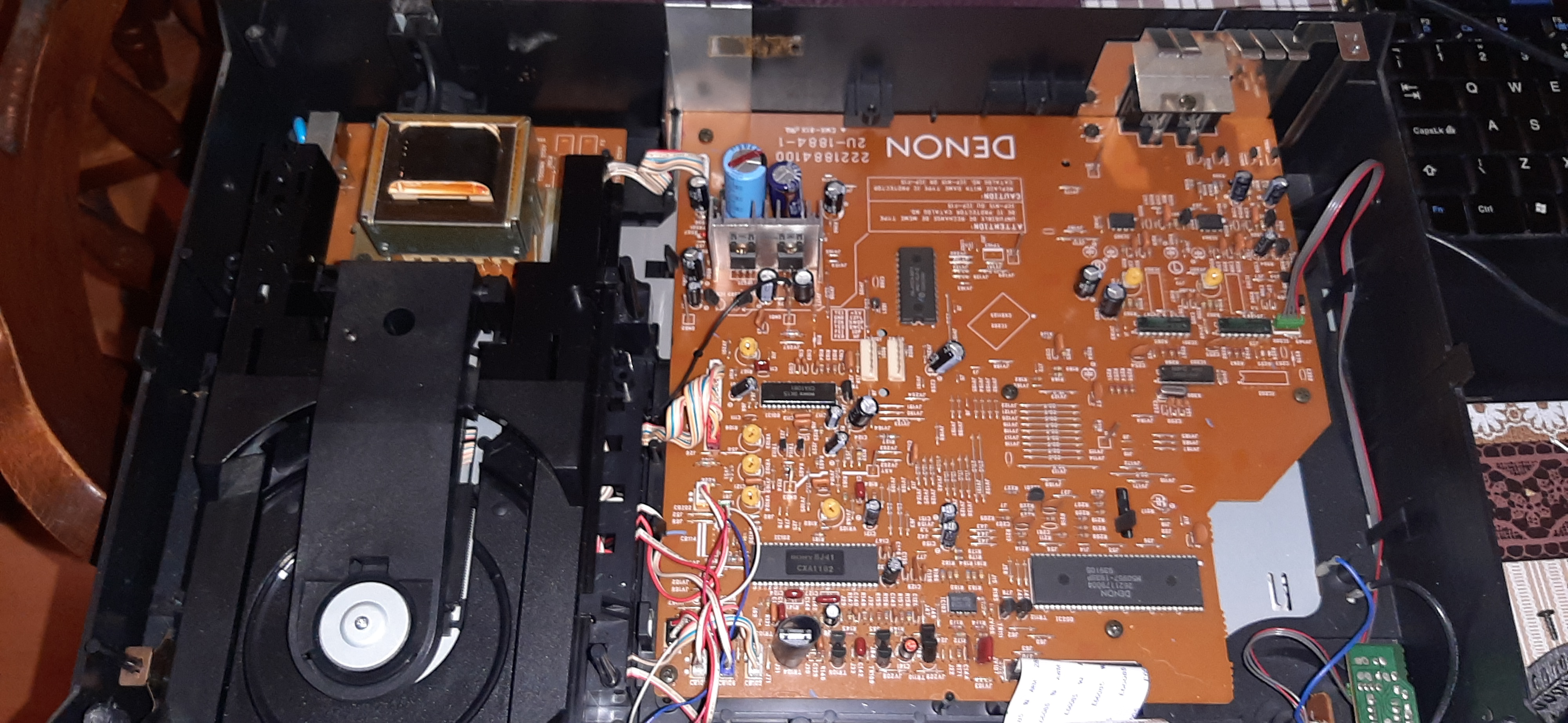
I was surprised to note how many discrete components there were. It looked like this system was mostly hand made (pick and place machines struggle with through hole components). I originally thought that this deck was from the 1990's but this makes me think it is 1980's, making it a very early system (CD's only became widely available outside of professional industry in 1984 or so).
Unfortunately a cursory glance of the logic board saw no visible issues with any of the capacitors, which meant I would have to dig deeper. First thing I did was to see if I could find a service manual online. I was in luck as I found one on archive.org, a mirror of which can be found here.
The service manual is very good, not only does it list the components it also gives you the "debug" mode commands and full schematics. In addition it lists test points with the expected waveforms at each point. With my multimeter and oscilloscope I checked each of the test points I could, only to find that the values matched with what the manual said they should be.
Next step then was to go through the entire schematic diagram. In addition to the test points, the manual gives you values and waveforms in the schematic for specific pins and connectors. More fiddly to test so I presume it was only for serious debugging. As it is my suspicion that the issue is power related I duly started debugging starting from the mains transformer, stepping through the power supply.
While debugging the power supply I found my first oddity. According to the service manual the power supply provides both positive and negative voltage in the form of ±5v and ±10v. While I saw +5v and -5v as expected, the ±10v lines were unbalanced, giving me -8.3v and +13.4v. As this is the first mismatch I had found I started detailed debugging of the power supply in order to try to work out the cause.
In the end I discovered what the problem was. On the schematic the diode bridge that converts AC to DC has two 2200μF 16V smoothing capacitors listed, each of which feeds into the corresponding side of the power supply (to provide the regulated positive and negative voltages). On the logic board the power supply had two 2200μF capacitors but I noticed that they were different sizes, with one a light blue colour next to one darker blue colour, as shown:
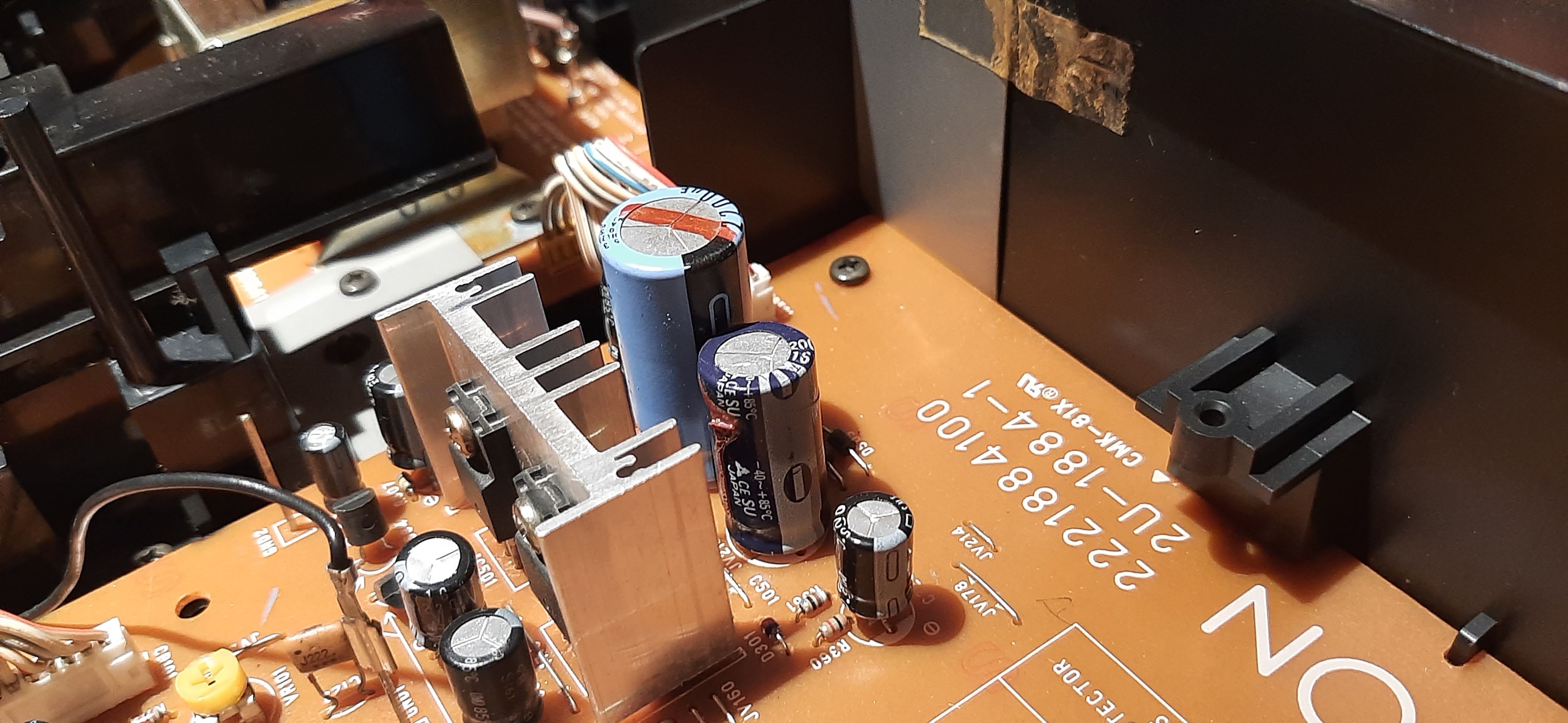
I noticed the larger light blue capacitor was rated at 25V, not 16V as in the schematic. I realised the light blue one is not original. Possibly this deck blew a capacitor and someone replaced it. However it is of a higher voltage. Now if the source voltage was regulated at 16V this probably would not have been an issue but we have a pulsing DC voltage from the diode bridge. This meant that the 25V capacitor would most likely have a higher average voltage than the 16V capacitor, which could be manifesting in the unbalanced output at the other end.
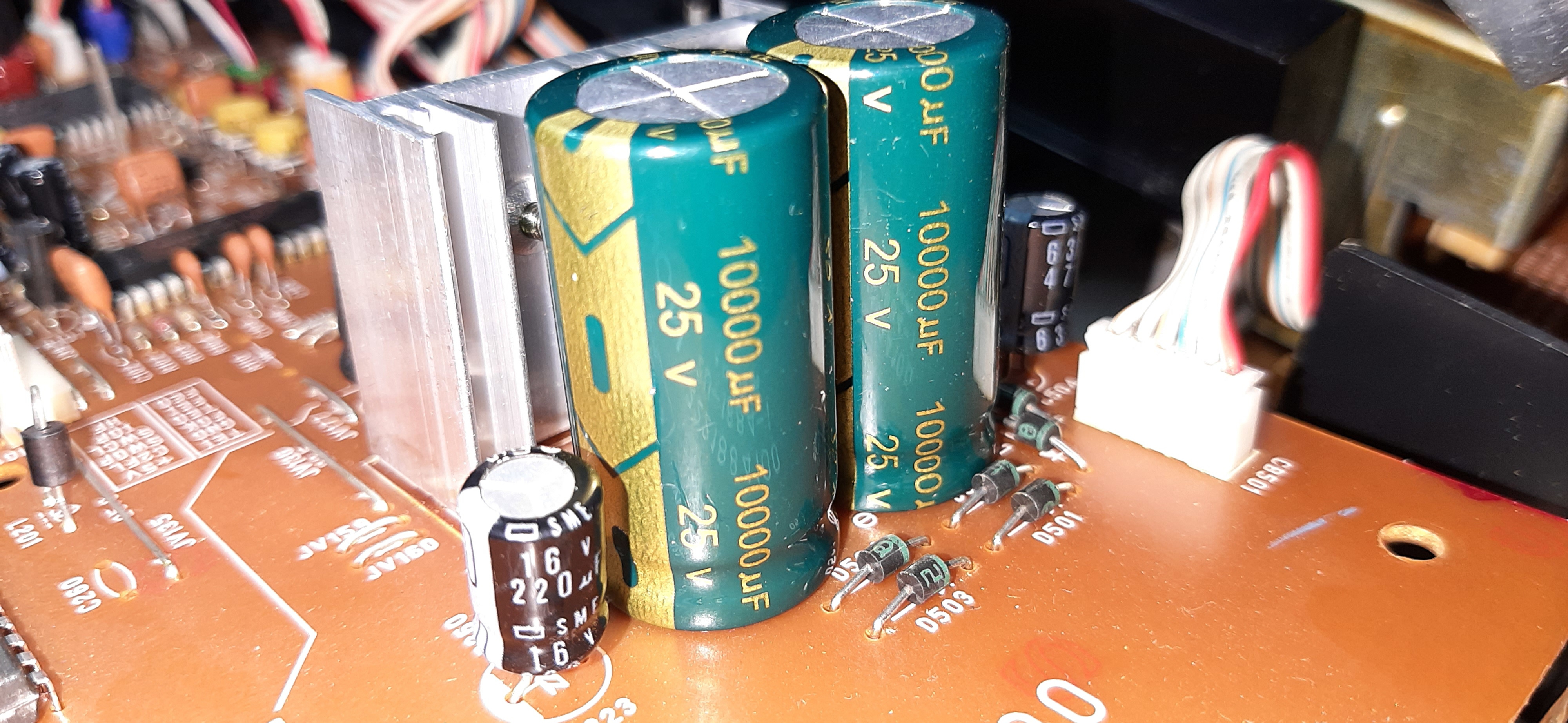
To test my hypothesis I replaced the capacitors. I had no 2200μF 16V capacitors, so I replaced both with 10,000μF 25V LowESR capacitors instead, figuring it is better to go with larger than smaller capacitors. I suspected that the output voltage would be higher than original, but I also suspected that the system would tolerate a higher balanced voltage better than a lower unbalanced one. Here you can see both the capacitors replaced:
Power was restored and the system came up without any VFD flashing, which was a good sign. Testing with the multimeter gave me ±11.2V, meaning we had balance on both positive and negative lines. Further tests showed that the deck now functioned perfectly. Only thing I noticed is that when turning off the deck the VFD takes longer to fade out, probably due to the larger capacitance. However that also provides us with more reserve energy for operation.
Overall things are looking good, the fix was cheap and easy to do. It seems someone knew enough about electronics to replace the failed capacitor, but not enough to know to replace both of them in a balanced power supply such as this. I shall keep using the system and see if there are any other issues that crop up.
February 2024
I wrote this update to say that so far the system seems to be working perfectly. So my CD collection will not be relegated to storage! Now that I have a CD player I actually listen to my CDs more often. I find it particularly good when I am not sure what I want to listen to. It is much easier to just cast my eye across the spines of the CDs to contemplate my next album then it is to go through all the folders on my digital music library. Plus it is nice to see the actual artwork and read the inlay while listening to the CD. Small pleasures I had forgotten about.
I do find that it struggles to seek CDs sometimes and it is very sensitive to scratches. Reading the manual further I find that there is an entire procedure to adjust core functioning of the system, marked as PLL, Tracking, Focus and Gain. It is possible that whoever fitted the capacitor also twiddled with the adjustments in an effort to make the system work so I would like to go through the adjustment myself to verify/correct if needed.
Unfortunately for some of these adjustments you need a reference audio disk "CA-1094". Looking online I find no copies of this disk, and Denon's website does not even mention this model anymore so I suspect it has been lost to time (anyone out there with a copy, do get in touch!). I also need a signal generator for some of the adjustments. As such I will look to do this at a later point when I have the tools I need.
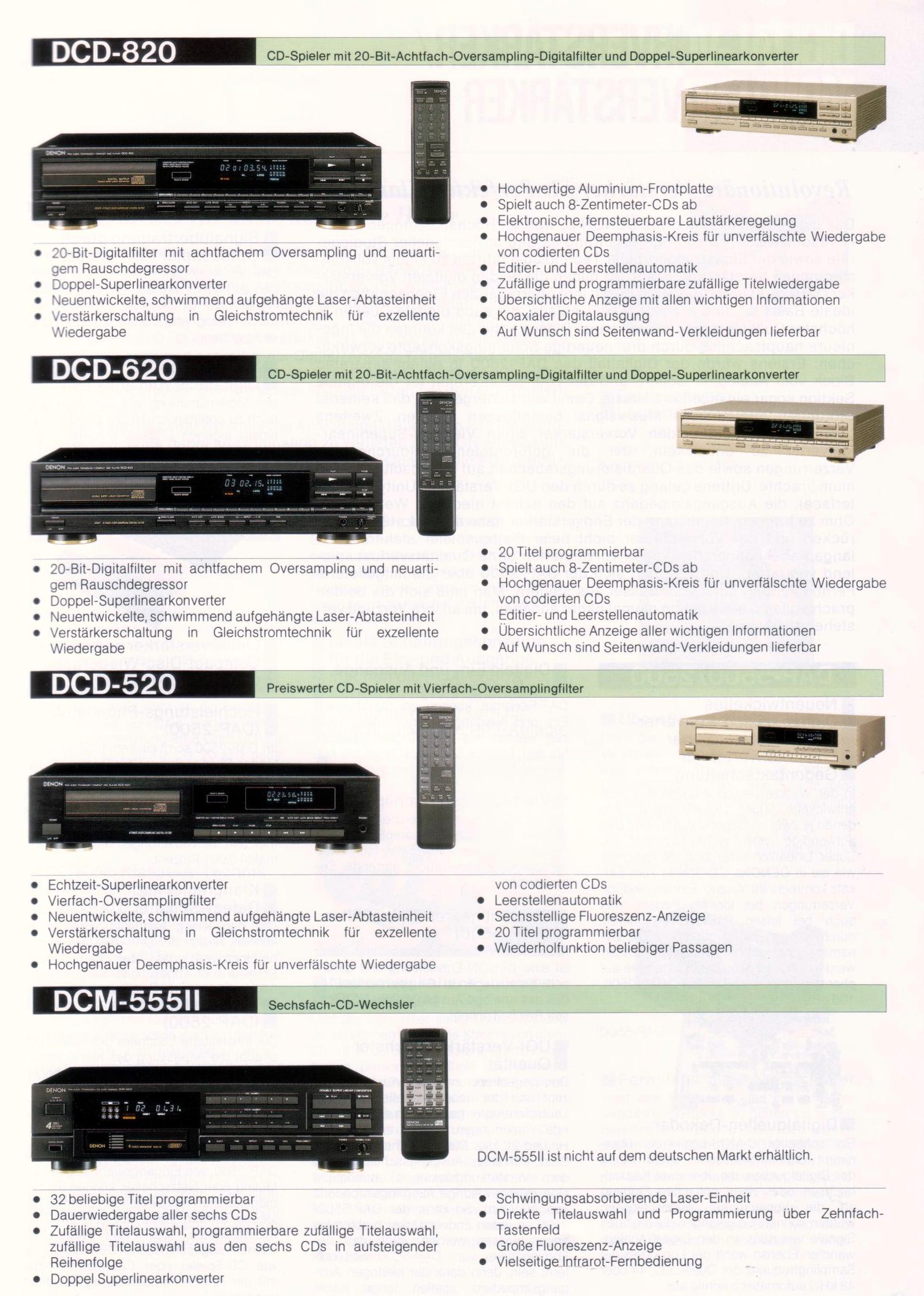
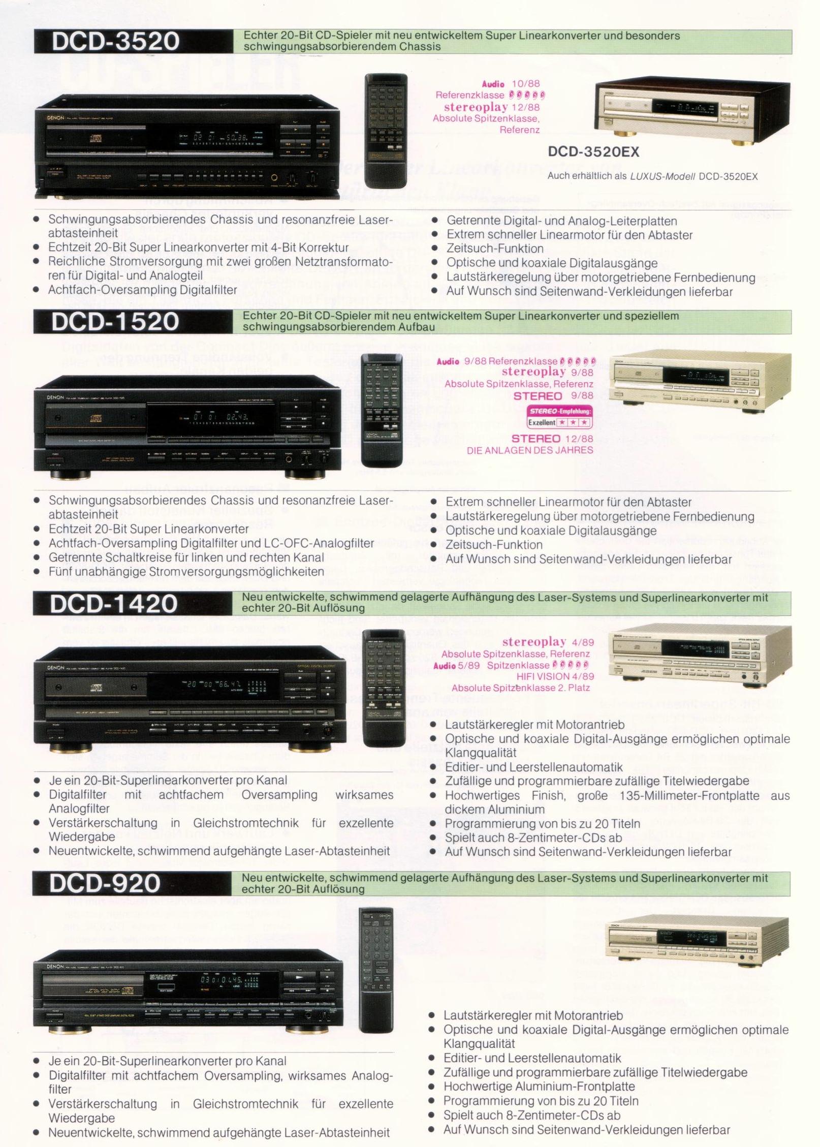
Reading online, is seems the CDP-620 was part of a whole family of "Double Linear Converter" devices released in 1988, only 1 year after the official CD standard came into existence (the IEC 60908 CD-Audio standard was ratified and adopted in 1987). This is one of the earliest systems to guarantee the ability to play any standard Audio CD. The family can be seen here and here. The images are originally from the hifi-wiki pages for the DCD-820 and DCD-920.
Unfortunately the DCD-620 is the only one of that batch that does not have a SPDIF output (the DCD-820 has coax, the DCD-920 has coax and TOSLINK optical). However while reading the service manual I noticed the decoder chip (a Sony CXD1125Q) mentioned a digital output on pin 27. Put that in my search engine to find a detailed datasheet and the first thing that comes up is a forum post for modding a Sony CDP-270 to add SPDIF which uses the same chip. It was apparently an easy mod to enable the output signal, which brings me hope that it will be just as easy for this Denon.
The DCD-620 has its own entry in the hi-fi wiki here, where it mentions that it originally cost 595 DM (Deutsche Mark). I am curious as to how much that would be in today's Euros, but as the Euro replaced the DM ages ago I can't do a direct comparison. It will require some calculation and thinking to work out, but considering that CDs were the hot new technology of the era it was probably quite expensive.
Saying that, looking at prices now (February 2024) the DCD-620 is noticeably cheaper second hand than the 820 and 920. The DCD-620 seems to selling for between €25 and €40. The DCD-820 from €40 to €120, and the DCD-920 from €90 to €180. This most likely reflects on the improved analogue stages of the better models, plus the digital output makes them good transports for modern DACs.
Considering these systems are now 36 years old, the fact they are still available for sale for solid prices are testament to being a decent bit of kit (otherwise they would have long since been junked).
June 2024
Been using the deck for a few months, playing through my CD collection. I have noticed that it struggles with certain CD's that don't have any scratches on them.
I also noticed that sometimes I lose one analogue channel, requiring me to reach round to the rear of the deck and twiddle the cables. I think one of the phono sockets is damaged, so at some point I will have to dismantle the deck and have a look at this more closely.
July 2024
Phono socket repair
So I had some free time in July and decided to take the deck apart again in order to investigate the phono socket issue.
Once the deck was dismantled and I got the motherboard out, it became clear to me that the issue was not with the socket itself, but that the socket had partially detached from the PCB. Further investigation showed that the socket had been removed and improperly resoldered in the past. There was not enough solder so the joints were dry and brittle. With the flexing of the sockets with plugging/unplugging cables the connection was eventually broken.
So I re-did the solder joints, using proper (leaded) solder and now the socket is fast attached to the PCB as it should be. As I already had the board out I went over the PCB, checking for any previous bodges and fixing them up. There were a few other places that needed resoldering as well. I can only presume that whoever incorrectly changed the capacitor above also bodged these areas.
Once this was complete I tested out the deck and both channels now worked perfectly. As I had the system dismantled I thought about improving the sound quality. Reading online showed that some people improved the sound output quality by replacing capacitors (as the linear PCM DACs are apparently decent), but considering I had a dedicated DAC where I put in effort for good sound quality, I did not think improving the audio stage of the CD player is the best way forward.
So I decided to first see if I could get a digital signal out of the deck, bypassing the analogue stage completely.
Adding SPDIF output
So with the board already out I decided to investigate enabling SPDIF on my deck. From the brochure I know the model decks above this one had SPDIF, from searching online I know that the SONY CXD1125Q supports SPDIF output if the correct pin configuration is made.
As such I suspected that this deck most likely has SPDIF already configured, but the signal is just not brought out of the case. I base this on the premise that to reduce costs of production Denon most likely used the same production line for all the PCBs. The only difference in models would be the configuration of the supporting electronic components for different models (as well as quality of components, the higher end models most likely had better analogue stage).
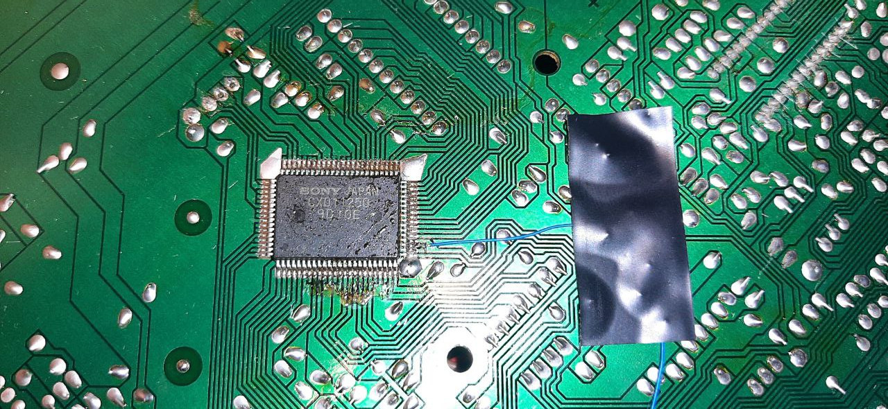
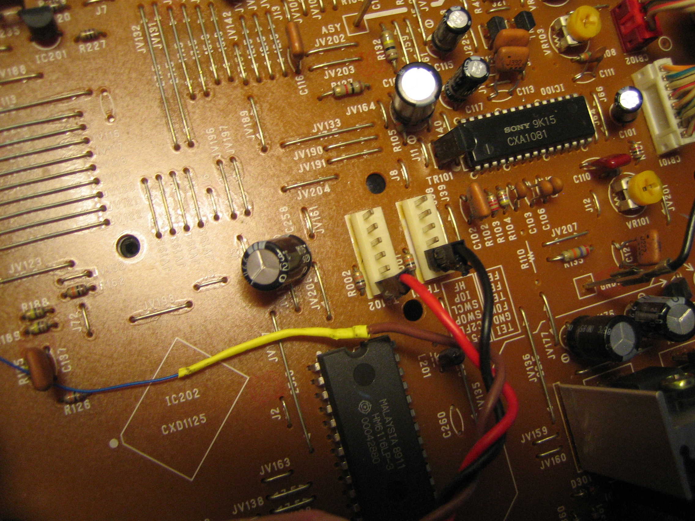
My best source on how to do this in fact was the Denon service manual itself. There they gave us the pinout of the CXD1125Q, with each pin named. Pin 27 was helpfully named "DOTX Digital out Output".
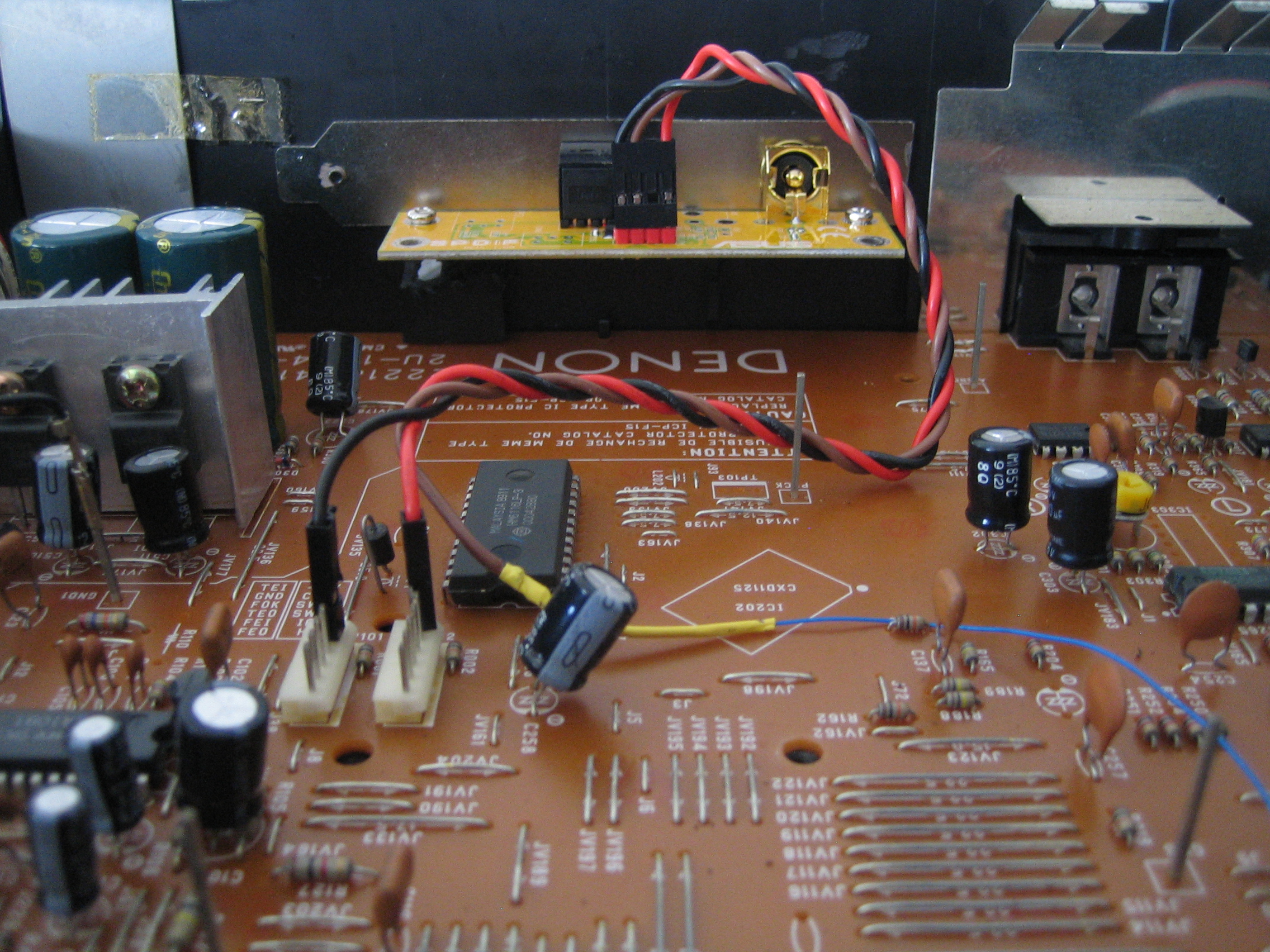
So I carefully soldered some thin solid core signal wire to pin 27, got my scope out and checked if we got any signal. The results were promising, a clean TTL digital signal was visible, and when a CD was playing the patterns looked very much like what I expected. I taped down the wire to prevent movement as shown below and re-assembled the motherboard to the case.
The next stage was to turn that TTL signal into something that is acceptable to standard SPDIF interfaces. While we could make a DIY interface there is an easier "ready to use" way of providing compliant SPDIF output.
As luck would have it back in the late 1990s/early 2000s ASUS provided a little optional daughterboard for its computer motherboards. It would hook up to SPDIF TTL pinout on the motherboard and convert it to TOSLINK and COAXIAL/RCA SPDIF for you.
This became so popular that other motherboards started to include a compatible "SPDIF header". It has since become a de-facto industry standard and almost 30 years later you can still buy these daughterboards, both ASUS OEM and third party clones.
As it uses TTL signals, I believed that it would work just as well on this deck as it would on a PC SPDIF header. So I decided to give it a go and bought the OEM ASUS board brand new:
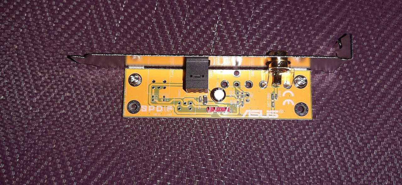
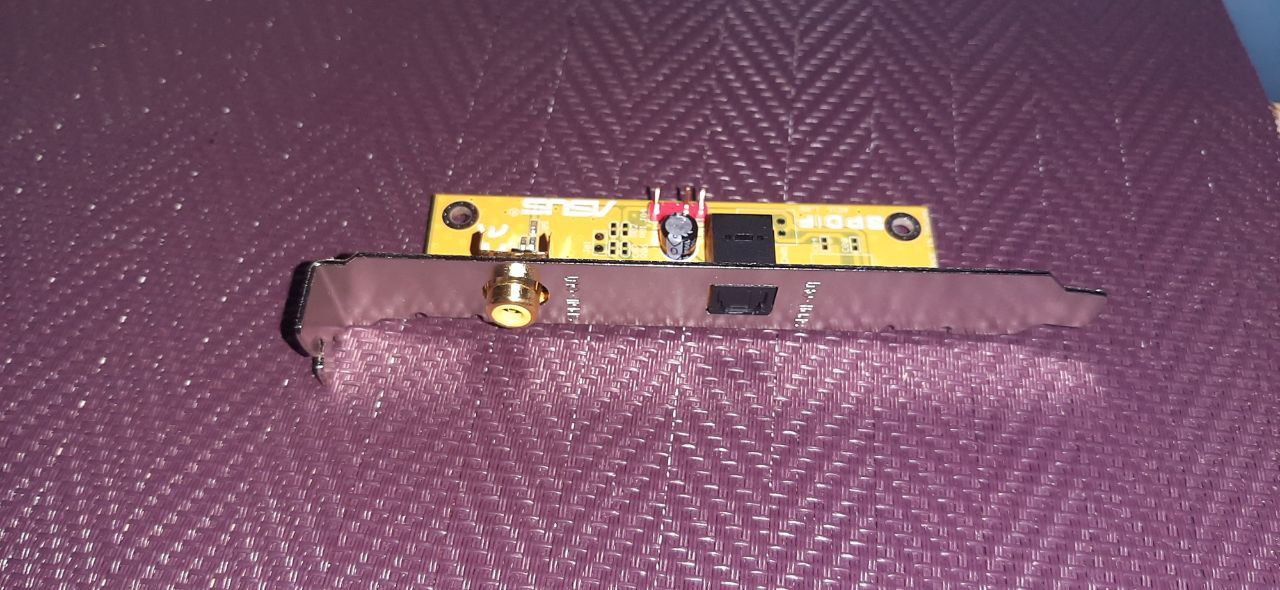
As you can see interfacing is really simple. You have three wires, +5V, GND and SPDIF TTL input, and it outputs standards compliant signals via optical TOSLINK and coax. It also nicely comes with a full height PCI mounting bracket which makes it easy to panel mount this board for a professional look.
As shown above I hooked up the +5V and GND to the pins already soldered on the deck PCB, and the SPDIF wire is soldered to the thin signal wire, with heat shrinking for insulation and to keep the mechanical bond together. For testing I just rested the daughterboard on the case.
With that I powered the deck on, played a CD and tested the RCA connector with my scope. The signal was nice, clear and within specifications for voltage output. I then plugged my TOSLINK optical cable to my DAC and was greeted with music. It works perfectly! For completeness sake I tried with the RCA socket as well, and can confirm that works fine too.
All in all this was a far easier modification than I expected, it turns out SPDIF is all configured on the main PCB, you just have to take the signal wire to a TTL->SPDIF interface and there you go. Now the deck can be used as digital transport for your DAC.
I can also say that it does sound noticeably better when using SPDIF and my DAC. I now have both the phono analogue and SPDIF->DAC digital wired so with one knob I can switch the sources to compare. It is a marked improvement, especially considering how easy a modification this was
The next step was to mount the interface onto the rear of the case. First thing I did was dismantle the SPDIF bracket from the PCB, then I marked out the areas where I will cut and drill. I decided to attach the metal bracket to the Denon case by screws, so that it can be removed in future to remove the motherboard again.
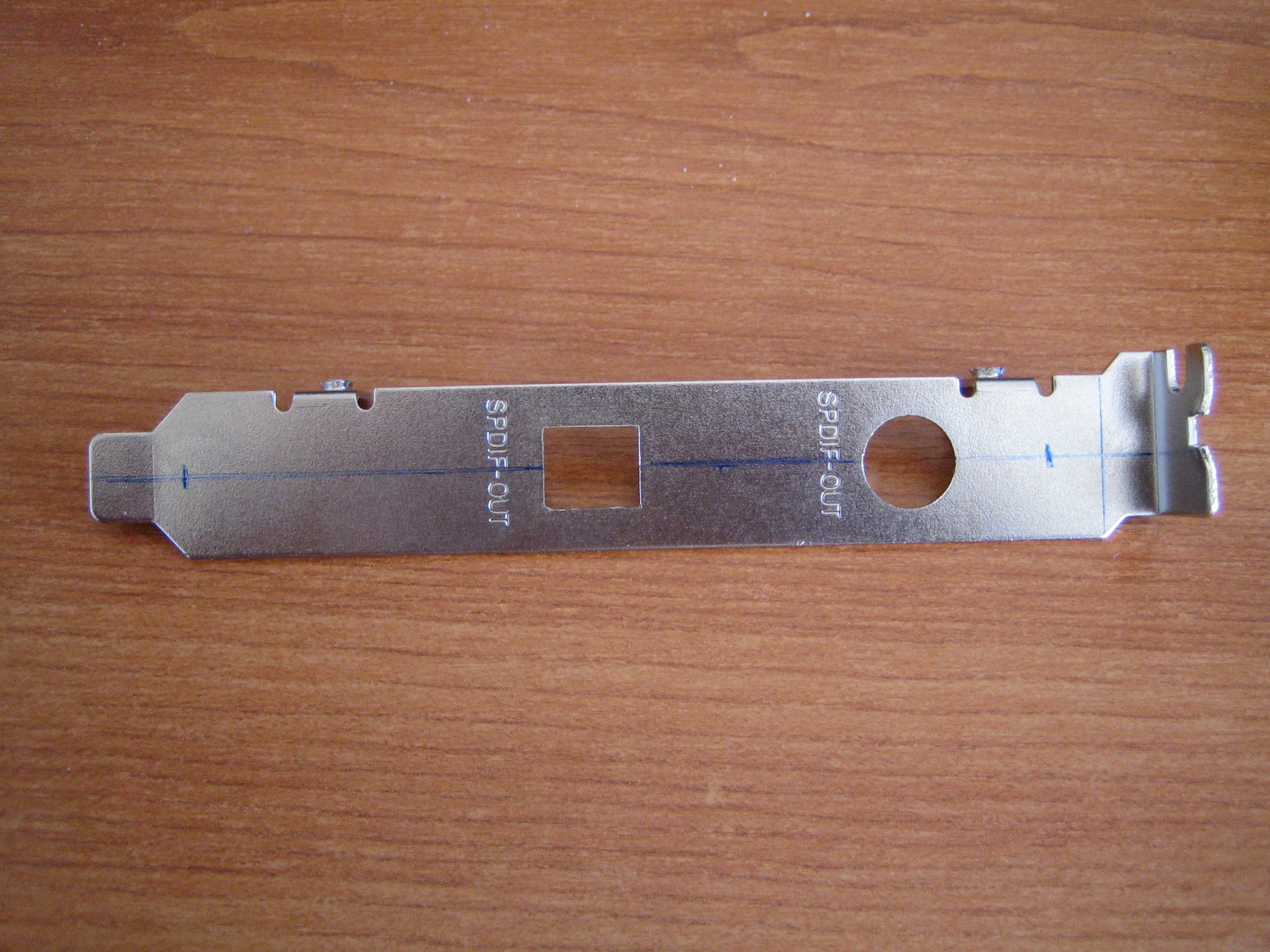
Above you can see the areas marked out
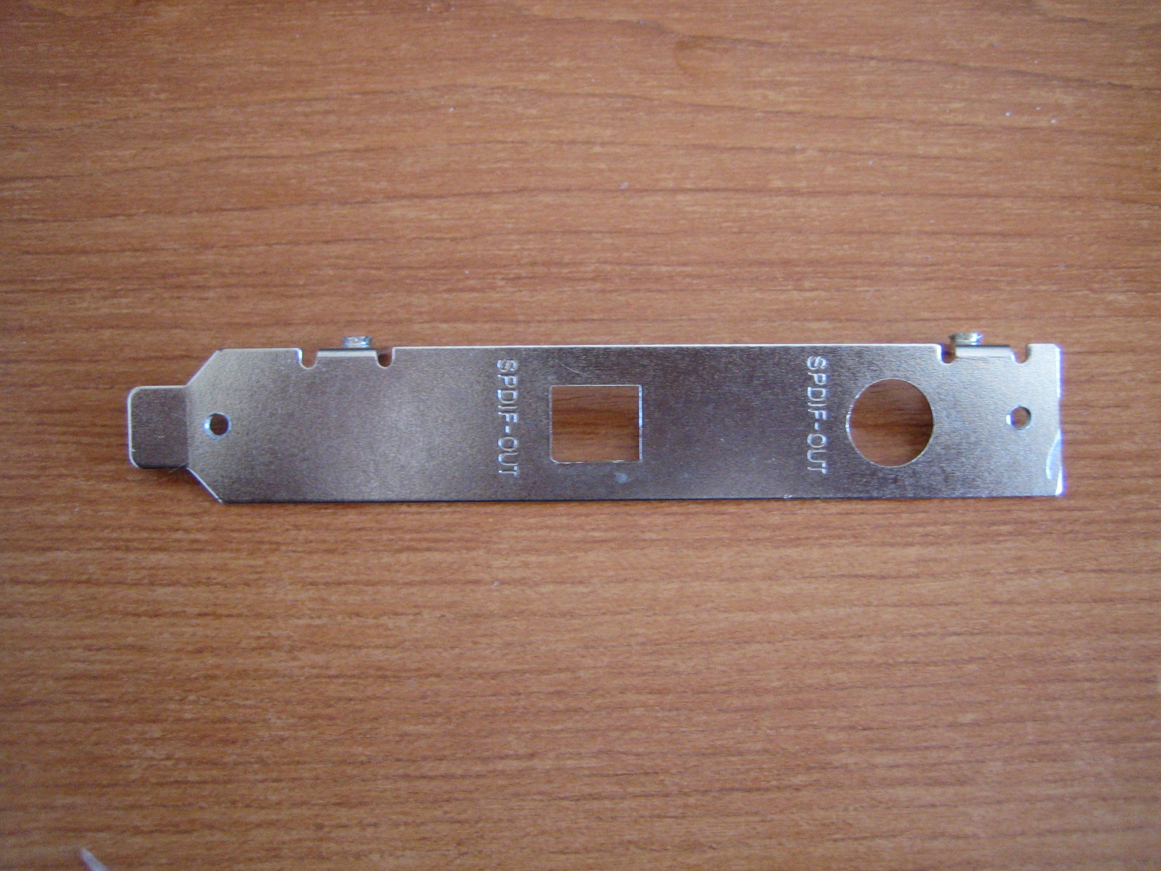
And the final result, ready for mounting. I drilled and tapped for M3 screws as that is the standard size for computer screws, which means I have a huge pile of them available.
The next step was to make a pattern from the bracket that I can use to correctly drill holes on the back of the Denon case. It is important to get this correct, as any inaccuracy here will translate onto the final result.
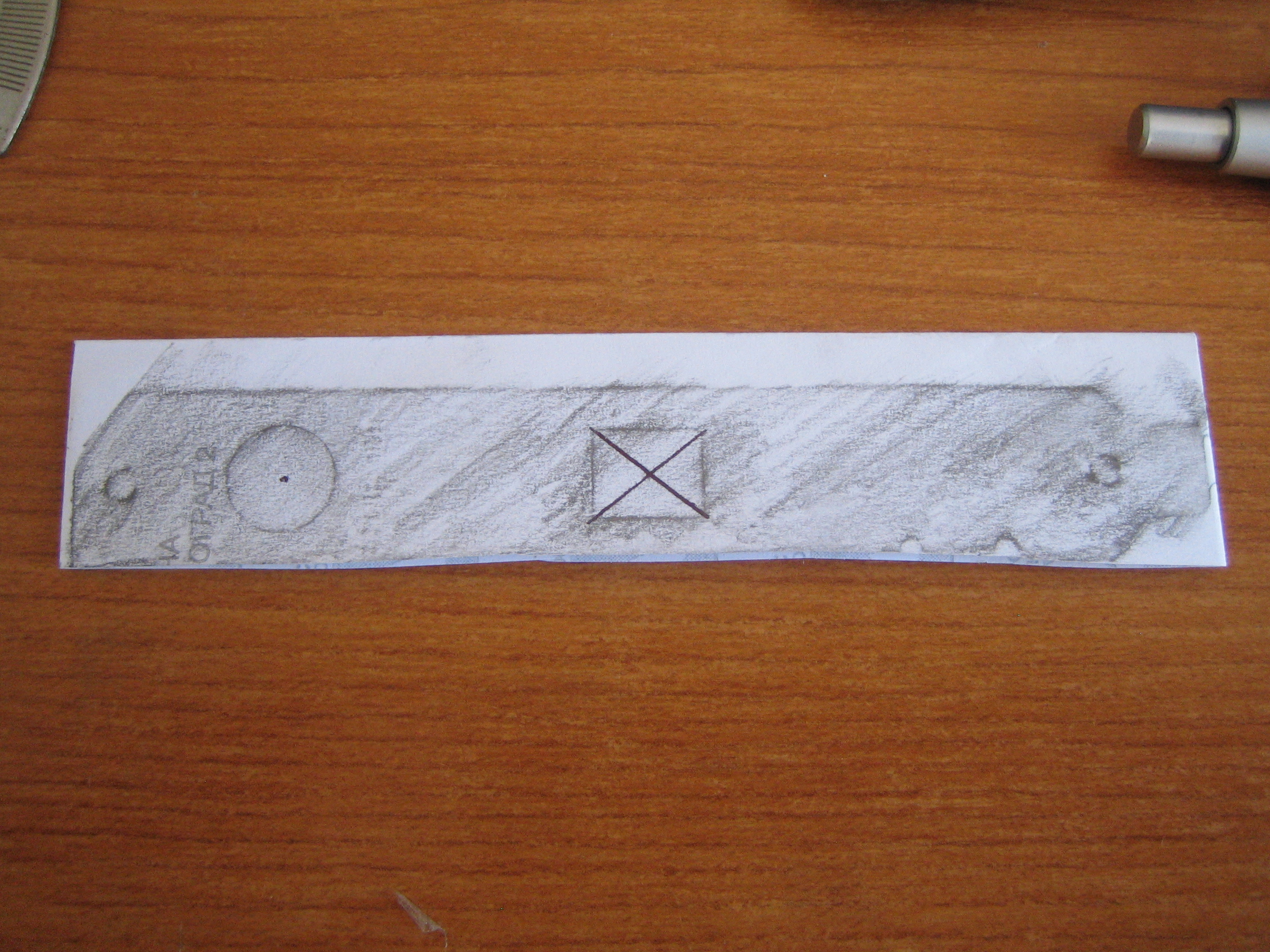
Here is my result, I made use of normal paper and a pencil to make a single use pattern. This was then mounted against the rear of the Denon case as shown in the photo below:
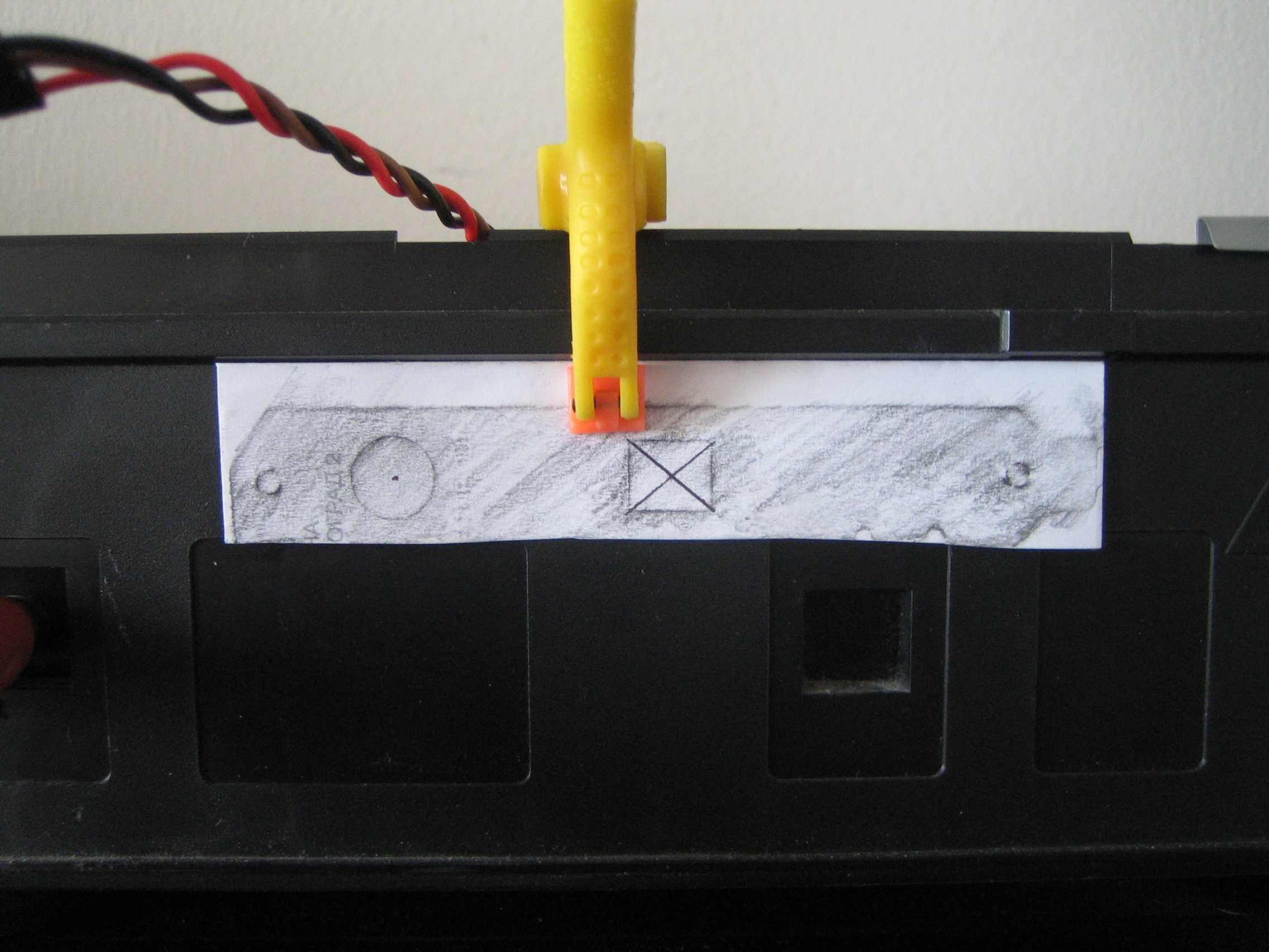
As you can see I used the existing moulding as a reference to keep the pattern level horizontally and it was positioned so it would not foul with the earth/noise isolation metal panels in the case.. The holes were then drilled. I wanted to use a 13mm drill bit for the output plugs as that would give enough clearance for all cables and it is easier to make good holes rather than squares. However my bits only went up to 11mm. Therefore I drilled both for 11mm and then I used a file to manually "square out" the TOSlink connector. It is nowhere near ideal but it is the best I can do with the tools I have. The end result is shown below:
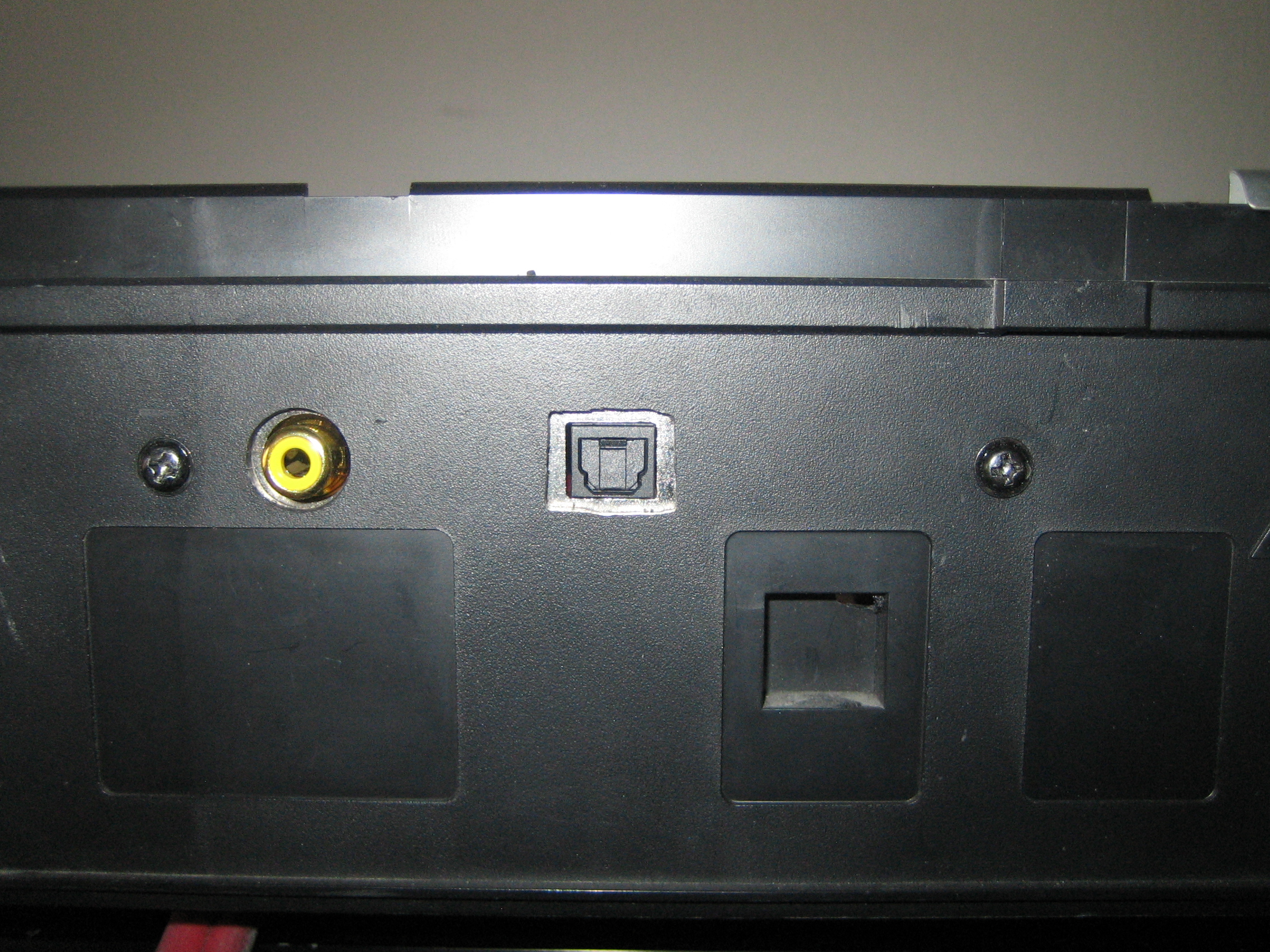
I had two black M3 screws so used them so that it fits in more with the black case. You can see how the square is not perfect as it was hand filed but thankfully it is on the rear of the case so it won't be visible.
While mounting I also realised I made a mistake. I put the bracket too low down, which meant when it came to mounting the PCB hit against the moulded indentations in the case. These indentations are not used on my deck (I suspect they are for the OEM SPDIF modules) so I had to cut them out with my rotary tool. If you do this mod I would recommend you mount the bracket higher up so the SPDIF PCB will not foul on the mouldings.
And the completed system mounted and wired up, as seen from the inside:
And that is it. I've been testing it the last a few days and it is working great. The only thing that caught me out was that one of my optical cables has a round connector, which means I can't insert it into the TOSlink socket. It doesn't fit by 1-2mm, so the larger drill bit would have solved this had I had it. It is a minor thing as my other optical cables work fine, plus I will be using the RCA connector for this deck long term where there are no fouling issues.
August 2024
Things are still going well with the SPDIF output, however now that I am listening to my CD collection more, I am finding more and more CDs which the deck has problems reading. As mentioned earlier in this article I have suspected for a while that the decks calibration may be wrong. Either because a previous owner twiddled with the settings, or the new higher output voltage from the PSU had altered the parameters and thrown the system out of calibration.
I however did not want to fiddle with the calibration settings due to not having the reference disk "CA-1094". Having read more online I came across this thread which explained a bit more to me what a reference disk is. It turns out the waveforms on the disk are not the key to calibration, but how the disk itself is mastered. Turns out these disks are speciality pressed to a highly accurate level and to close tolerances of the red-book standard. The goal is for these disks to be a reference that would allow any mass produced CD to play on a calibrated deck.
The downside of this is that you can't just burn an image of the reference disk onto a CDR. It is the actual mastering process that does the magic for calibration. I guess this also explains why you can't find any image of such a disk online as such an image is effectively useless. It also means that these reference disks are correspondingly very expensive (€200 or more). Far in excess of making sense for me to buy one just to calibrate my deck.
I thought to just take the deck to a Denon service centre for calibration (if they even would do calibration of such an old deck) but in my corner of Europe there is no service centre to even ask. So that idea fell by the wayside.
So I just left the deck alone but eventually sods law brought me to a CD in my collection the deck would not play at all. It just could not play it. There was nothing wrong with the CD. It was a pressed CD with no scratches but for some reason it could not be read.
At this point I realised that the CD that I cannot play at all could be useful as a reference. I already have disks that play perfectly, and those that it struggles with. Between these three disks I could in theory "average out" the calibration so that the deck can play my collection.
Having a look at the service manual, I felt that the only things I had a hope in hell of calibrating would be the "PLL Adjust" and "Tracking offset". Therefore the first thing I did was take a photo of all the current calibration settings (I took a photo of all the pots the service manual says to use for calibration). This is very important as it gives you a "last known" standard to revert to if your changes actually make things worse (which happened with me during this task, multiple times).
Once the photo was taken I started on the calibration. Following the manual the first thing I checked was the PLL frequency. It is supposed to be 4.32MHz ± 10KHz, but mine was completely wrong. First issue located and corrected, but my deck still did not play the disks properly.
The second was the "tracking offset", which does require the reference disk. I would not have touched this if the deck worked but as it doesn't I went for it. I set up my scope to do average sampling which should have a similar noise filtering characteristic as the filter circuit in the manual, and then alternated between the three CD's, altering the offset tracking until the waveform amplitude was as equal as possible.
Once this was done the deck played all three disks, so we had an improvement. Still some tracks it would skip on and I did the only thing I could, I randomly tweaked the calibration pots and re-listened to the tracks (and then the entire CDs) until they all played back perfectly. Once done I played the other disks that had known issues but I did not have use for the calibration, to make sure they played properly as well. After every tweak I would then go through the original three CDs I used as references and then the rest.
Saying this is a long process is an understatement, it took days and I got a bit fed up of listening to the same albums on loop. However by the end the deck played all the disks perfectly. I then played a few other randomly chosen CDs from my collection and they played well too. So at this point I think I am done with the calibration. I assembled the deck and will use it now. If I come across another CD it cannot play I will revisit the calibration.
If there is one thing I can recommend to you, is do NOT fiddle with the calibration settings on your deck. Without the proper tools it is insanely difficult to get it right and this is just me trying to calibrate two of the settings. I was lucky that the more complex calibration seems "good enough" that just adjusting the offset tracking was enough to make my CDs readable. Not to mention that before I got the CDs to play properly I actually made things worse (the deck stopped properly playing disks it could read fine before) but I was saved by the photos of "last known" settings I could revert to before retrying. Seriously, don't touch it unless you absolutely have no choice and don't mind possibly ruining your deck. I effectively got this deck for free so it would not have been the end of the world if I ruined it, but things may be different for you.
However things are looking good for my deck right now. The fact the tracking offset fixed the issue (which is to do with equalising the waves amplitude) makes me think this must have been changed by the previous owner to compensate for the unbalanced supply voltage. That must have shifted the waveform in one direction, which was shifted back when I equalised the supply output again.
Hopefully this will be the end of the saga of getting this deck working properly and now I can enjoy my CD collection :-)
Links
While doing my research I also found some more links that I found a useful reference, even if I did not make direct use of them for repairs. They are posted here in no particular order:
diyaudio thread on reference/test disks
The Denon DCM CD Player repair thread
A general overview on troubleshooting and repairing CD players
Ken Clements - Understanding And Servicing CD Players (1994), e-book from Archive.org (torrent)


